
Receiver Prototype
This project is a pretty big deal for me. Over Christmas I bought a Carvera desktop CNC mill and have been wanting to make some projects with it. A key feature of the Carvera is the ability to make printed circuit boards (PCBs) with a fine engraving bit. It also has a laser etcher, automatic tool changing, dust collection, is really quiet, and is definitely worth the price. But enough about the CNC machine. Another thing I’ve wanted to do is to design a radio using commonly available parts (read: available with Amazon Prime shipping). There’s a common type of radio design called the Tayloe Detector (named after the designer, Dan Tayloe) and it is often used for software defined radio due to the way it can be used with a computer sound card. I am also a amateur radio operator (eventually I’m going to stop reminding you of that) fact.
So the stars were pretty much aligned for me to do a radio project this winter. I didn’t know anything about PCB design, but I figured it out. It took me several hours over the course of about a month to pick out the parts that I wanted, design a PCB, cut it out on the Carvera, put it together, troubleshoot all the issues, and get it kind of working. It kind of sucks, but it proves that I can complete a project and I learned a lot along the way. I call this the “Rx v0” because I didn’t really think it was going to be a good design or be competitive with other radios. I’m not sharing the project files because you shouldn’t build this. But maybe my next project will be good enough to share the files. But here’s an overview of what I did:
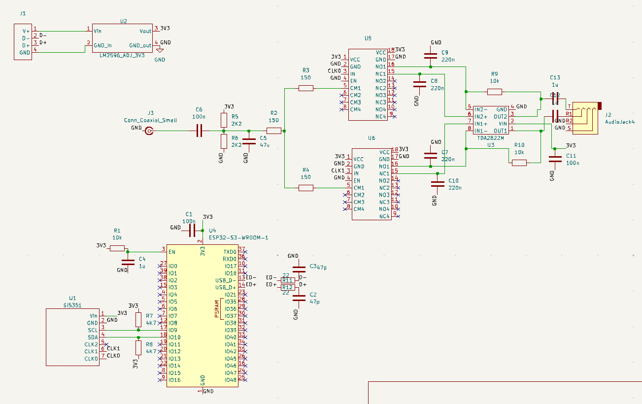
- Step 1 is to make a schematic. This is the easy part, because you get to tell yourself that you’re going to make all these electrical connections and ignore all the challenges of actually routing the signals on a PCB and doing the soldering. It’s also fun because you get to hunt down the parts you want to use and put together electical symbols for any of the parts that don’t exist.
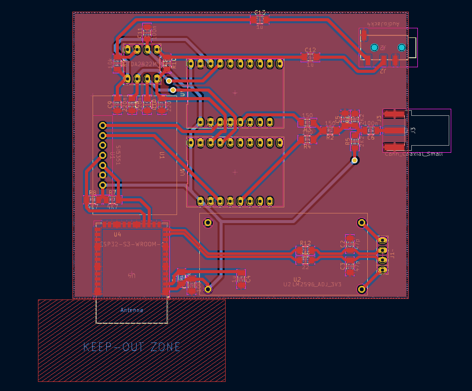
- Step 2 is to design the PCB. Hobby PCBs are either 1-sided or 2-sided, and I went with 2-sided because I can. This design wasn’t great because of the way I routed the signals- I thought I was being clever using the through-hole pins as vias, but it was a total pain to solder. Next time I’m going to solder through-hole pins on one side of the board and then place a via next to it. I’m also going to have bigger pads to solder on and larger gaps between my traces and ground plane.
-
Step 3 is to cut out the PCB. I don’t have an pictures of this, maybe in another post I’ll go into more detail about making a PCB on the Carvera. Before I do I’ll need to get a little more professional with my PCB making, but I’ll get there.
-
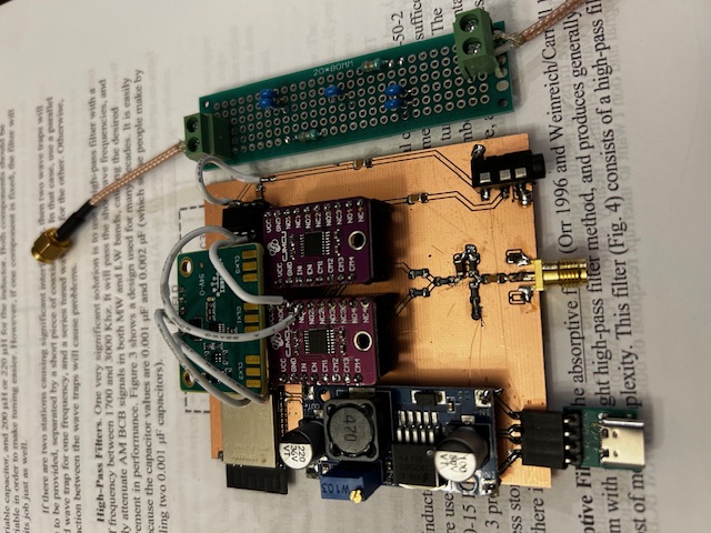
Step 4 is to solder everything down. One thing I tried to do was to use surface mount components for some things. That kind of sucked. I kept bridging my traces. I got to the point where I checked for bridges after every single solder joint. It went slow but I got it done, with a few mistakes. I might use only through-hole components for my next design. The five white wires in the picture are fixes where I wasn’t able to solder correctly on the pad, and had to resort to the wire fixes.
-
Step 5 was to troubleshoot. It was a lot of work. I had placed my TDA2822 amplifier in backwards. I had a shorted connection I didn’t catch (but only one). The clock generator board had a different pinout than I was expecting (fixed that in my code). I had to write code to tune the clock generator to a certain frequency. I had to calibrate the clock generator. The front end was totally overloaded from a 50 kilowatt AM radio station near my house, so I had to build a filter to block out the AM radio band.
-
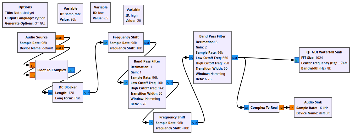
Step 6, writing code, kind of went alongside step 5. I wrote code in Arduino for the ESP32-S3 module to set the clock generator frequency. I also made a project in GNU Radio Companion to sample my computer’s audio line in and do some digital filtering and processing. Here’s a screenshot of the GNU Radio Companion project.
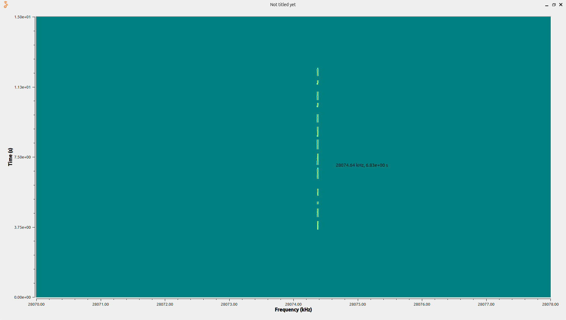
- But in the end, I got a “working” receiver! I haven’t picked up any signals over the air, but I did detect my Yaesu FT-950 transmitting into a dummy load placed near the input port. Here’s a picture of the (heavily filtered) FFT waterfall as I clumisly keyed my callsign, NN0Y, using my microphone PTT as a straight key.
I’ll try to do a more detailed post when I have a design worth talking about. I just wanted to post this because I’m kind of proud of what I did. Have a good day!